|
This CHAPTER contains a listing and outline of the CONVERSATIONAL MILLING cycles available in KipwareM®.
Conversational cycles allow users to create G code for the specific shapes using only fill-in-the-blank forms ... no CAD model or drawing of any kind is required to create G code using these cycles. They are arranged in this listing on no particular order and the list is current as of the current release.
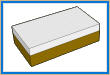
FACING ... Square / Rectangular Stock
This cycle creates G code to machine the top surface of square / rectangular stock. Options include depth of cut in Z as well as rough mill only, finish mill only or both rough and finish.
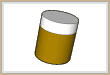
FACING ... Round Stock
This cycle creates G code to machine the top surface of round stock ... allowing for less wasted motion if a square / rectangular stock was used. Options include depth of cut in Z as well as rough mill only, finish mill only or both rough and finish.
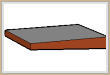
FACING ... Tapered Face
This cycle creates G code to machine the top surface of square / rectangular stock if the face is tapered ... allowing for less wasted motion is a flat surface was used. Options include depth of cut in Z as well as rough mill only, finish mill only or both rough and finish. A user defined angle of the taper can be input.
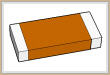
QUALIFY SIDES ... Square / Rectangular Stock
This cycle creates G code to machine the sides / qualify ends. Multiple options are available for machining one side ... both sides ... as well as depth of cut in Z and zig-zag or climb mill only or conventional mill only. Other options are available for rough mill only, finish mill only or both rough and finish. Cutter compensation ( G41 / G42 ) can be automatically employed.
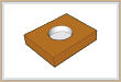
ROUND POCKET
This cycle creates G code to machine a circular pocket. Options include depth of cut in Z, user defined ramp in / down amount, as well as rough mill only, finish mill only or both rough and finish. Finishing the bottom or only the sides can also be selected. Multiple pocket locations can be input in this form for allowing an identical pocket to be machined at multiple locations. X / Y locations can be auto calculated for bolt circles, grid patterns or holes-on-an-angle. Locations can also be red in using an external DXF file or simply input manually. There is no limit to the number of locations that can be configured. Cutter compensation ( G41 / G42 ) can be automatically employed.
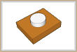
ROUND BOSS
This cycle creates G code to machine a circular boss. Options include depth of cut in Z as well as rough mill only, finish mill only or both rough and finish. Finishing the bottom or only the sides can also be selected. Cutter compensation ( G41 / G42 ) can be automatically employed.
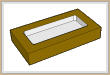
SQUARE / RECTANGULAR POCKET
This cycle creates G code to machine a square or rectangular pocket. Options include depth of cut in Z, user defined ramp in / down amount, as well as rough mill only, finish mill only or both rough and finish. Finishing the bottom or only the sides can also be selected. Multiple pocket locations can be input in this form for allowing an identical pocket to be machined at multiple locations. X / Y locations can be auto calculated for bolt circles, grid patterns or holes-on-an-angle. Locations can also be red in using an external DXF file or simply input manually. There is no limit to the number of locations that can be configured. The pocket can be ROTATED at any angle using a simple angular input on the form. Cutter compensation ( G41 / G42 ) can be automatically employed.
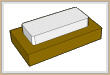
SQUARE / RECTANGULAR BOSS
This cycle creates G code to machine a square or rectangular boss. Options include depth of cut in Z as well as rough mill only, finish mill only or both rough and finish. Finishing the bottom or only the sides can also be selected. The boss can be ROTATED at any angle using a simple angular input on the form. Cutter compensation ( G41 / G42 ) can be automatically employed.
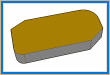
OD BOSS CONTOUR
This cycle creates G code to machine a square or rectangular boss with any chamfer or radius described an ANY corner. Options include depth of cut in Z as well as rough mill only, finish mill only or both rough and finish. Finishing the bottom or only the sides can also be selected. The boss can be ROTATED at any angle using a simple angular input on the form. The user can describe either a radius, chamfer or square corner an ANY corner of the boss. Cutter compensation ( G41 / G42 ) can be automatically employed.
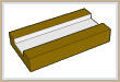
HORIZONTAL SLOT
This cycle creates G code to machine a slot in the X/Y horizontal direction. Options include depth of cut in Z as well as rough mill only, finish mill only or both rough and finish. Multiple machining options are available including : SOLID rough cutting where the slot is machined from solid ... SIDE rough cutting where cutting of the side walls only is required ... machining for THROUGH slots as well as CAPTURED slots. The slot can be ROTATED at any angle using a simple angular input on the form. Cutter compensation ( G41 / G42 ) can be automatically employed.
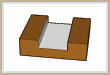
VERTICAL SLOT
This cycle creates G code to machine a slot in the X/Y vertical direction. Options include depth of cut in Z as well as rough mill only, finish mill only or both rough and finish. Multiple machining options are available including : SOLID rough cutting where the slot is machined from solid ... SIDE rough cutting where cutting of the side walls only is required ... machining for THROUGH slots as well as CAPTURED slots. The slot can be ROTATED at any angle using a simple angular input on the form. Cutter compensation ( G41 / G42 ) can be automatically employed.
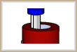
ID HELICAL MILLING
This cycle creates G code to machine a hole using a helical ( X/Y/Z ) motion. Options include depth of cut in Z as well as rough mill only, finish mill only or both rough and finish. Multiple hole locations can be input in this form for allowing an identical hole to be machined at multiple locations. X / Y locations can be auto calculated for bolt circles, grid patterns or holes-on-an-angle. Locations can also be red in using an external DXF file or simply input manually. There is no limit to the number of locations that can be configured. User can also select the quadrant to start the helical motion ... 0 degrees, 90 degrees, 180 degrees or 270 degrees. Cutter compensation ( G41 / G42 ) can be automatically employed.
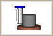
OD HELICAL MILLING
This cycle creates G code to machine a boss using a helical ( X/Y/Z ) motion. Options include depth of cut in Z as well as rough mill only, finish mill only or both rough and finish. Multiple boss locations can be input in this form for allowing an identical boss to be machined at multiple locations. X / Y locations can be auto calculated for bolt circles, grid patterns or holes-on-an-angle. Locations can also be red in using an external DXF file or simply input manually. There is no limit to the number of locations that can be configured. User can also select the quadrant to start the helical motion ... 0 degrees, 90 degrees, 180 degrees or 270 degrees. Cutter compensation ( G41 / G42 ) can be automatically employed.
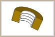
ID THREAD MILLING
This cycle creates G code to machine an ID THREAD using a helical ( X/Y/Z ) motion. Options include depth of cut in Z ( thread pitch ) as well as rough mill only, finish mill only or both rough and finish. Multiple hole locations can be input in this form for allowing an identical thread to be machined at multiple locations. X / Y locations can be auto calculated for bolt circles, grid patterns or holes-on-an-angle. Locations can also be red in using an external DXF file or simply input manually. There is no limit to the number of locations that can be configured. User can also select the quadrant to start the helical motion ... 0 degrees, 90 degrees, 180 degrees or 270 degrees. Cutter compensation ( G41 / G42 ) can be automatically employed.
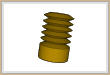
OD THREAD MILLING
This cycle creates G code to machine an OD THREAD using a helical ( X/Y/Z ) motion. Options include depth of cut in Z ( thread pitch ) as well as rough mill only, finish mill only or both rough and finish. Multiple boss locations can be input in this form for allowing an identical thread to be machined at multiple locations. X / Y locations can be auto calculated for bolt circles, grid patterns or holes-on-an-angle. Locations can also be red in using an external DXF file or simply input manually. There is no limit to the number of locations that can be configured. User can also select the quadrant to start the helical motion ... 0 degrees, 90 degrees, 180 degrees or 270 degrees. Cutter compensation ( G41 / G42 ) can be automatically employed.
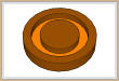
O RING GROOVE
This cycle creates G code to machine an O RING GROOVE on a flat surface. Options include depth of cut in Z, OD / ID of the groove configuration as well as rough mill only, finish mill only or both rough and finish. CLIMG or CONVENTIONAL mill can be selected when finishing is selected. Cutter compensation ( G41 / G42 ) can be automatically employed.
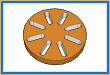
LINEAR SLOTTING
This cycle creates G code to machine a series of SLOTS along an arc. Options include depth of cut in Z, zig-zag cutting with Z ramping ... zig-zag cutting with Z plunging ... or one direction, ID to OD or OD to ID type cutting.
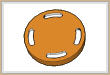
RADIAL SLOTTING
This cycle creates G code to machine a series of SLOTS along an arc. Options include depth of cut in Z, zig-zag cutting with Z ramping ... zig-zag cutting with Z plunging ... or one direction, ID to OD or OD to ID type cutting.
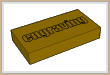
ENGRAVING
This cycle creates G code to ENGRAVE a user defined line of text. Two font styles are available and the line of text can be rotated at any user defined angle with a single angular input on the form. User can defined the height of the text, distance between the letters and depth of the text. A useful tool will auto calculate the length of the text string per the height and distance between the letters for positioning purposes.
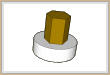
HEX MILLING
This cycle creates G code to machine a HEX shaped boss. Options include depth of cut in Z as well as rough mill only, finish mill only or both rough and finish. The user need only input the distance between the flats ... the software calculates the stock size and the complete tool path. Cutter compensation ( G41 / G42 ) can be automatically employed.
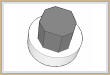
MULTI SIDE MILLING
This cycle creates G code to machine a MULTI SIDED shaped boss. Options include depth of cut in Z as well as rough mill only, finish mill only or both rough and finish. The user can define a shape with any number of sides and the distance between the points for the software to create the complete toolpath. Cutter compensation ( G41 / G42 ) can be automatically employed.
|

